Sonifex RB-DD4 4-Channel Digital Audio Delay, 32/44.1/48/88.2/96/176.4/192kHz Sample Frequency, 8 Seconds per Mono Channel/1.33 Seconds per Mono Channel Delay
SKU: SORBDD4
This item is no longer available.
Share:
Overview
Compare
Specs
Protection
About Sonifex RB-DD4
The Sonifex RB-DD4 4-Channel Digital Audio Delay allows to delay 4 mono channels of audio independently or together. Each channel delay is user selectable from multiples of common video frame rates or a user defined value set via the serial interface. The unit is perfect for synchronizing audio to video which has been delayed by processing latency. Using a front panel button, select which channel needs to be delayed. There is also an 'ALL' option which allows the selected delay to be applied to all channels. Then using another front panel button select the length of one frame of delay and the multiple of frames to delay by.
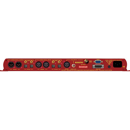
The connectivity is incredibly flexible, allowing three different types of connection to each input and output including AES/EBU, S/PDIF and TOSLink. All three different types of output can be used simultaneously. There is a monitor socket on the front panel which allows to listen to each mono channel, by front panel selection. Pairs of channels can be monitored (1 and 2 or 3 and 4) using a rear panel stereo option. There is also an option to attenuate the monitor by 12dB selectable by rear panel DIPswitch. Audio presence is detected and displayed for each channel around the INPUTS 1 and 2 and INPUTS 3 and 4 buttons.
The flexibility continues with many audio synchronization options. The digital audio output can be synchronized to either input, an additional AES/EBU reference input, a TTL word clock BNC input or an analogue/SDI video feed if used with an additional RB-SYA or RB-SYD board. Also the output can be synchronized to an on-board master clock, with a selectable frame rate. There are warning indicators on the front panel for loss of lock on both inputs and for the selected external synchronization. Selectable synchronization modes are as follows
Master Mode
In this mode the digital output sample rate is simply set by and locked to, the internal on-board clock generator. No sync signal is used or required.
Auto Sync Mode
In this mode the digital output sample rate follows the selected sync input. When the sync signal is not present the output sample rate will be set by and locked to, the internal on-board clock generator at the selected output frequency.
Auto Lock Mode
In this mode no output will be generated until lock is achieved with a sync signal. The digital output sample rate now follows the sync input. If the sync signal is removed then the output sample rate will be set by and locked to, the internal on-board clock generator at the closest frequency available to the previous sync input.
Slave Mode
In this mode the digital output sample rate follows the sync input. When the sync signal is not present the digital output is turned off. A powerful feature of the RB-DD4 is that by using the Sonifex SCi serial software, the unit can be programmed for different delay durations, levels and switching functions so that you can program the unit for your specific application. A rear panel DIPswitch configures the unit to be controlled serially. Contact Sonifex for further information if you have a particular requirement that isn't catered for by the RB-DD4 as standard. The RB-DD4 has been designed to have a passive signal path through the main input, so if power to the unit fails, signal inputs 1 and 2 are routed to outputs 1 and 2 and signal inputs 3 and 4 are routed to outputs 3 and 4. This is essential for applications such as installation at transmitter sites, where a power failure to the unit should not prevent the audio input signal from being output to the transmitter. Please note that this is not true for the TOSLink outputs which are muted.