

This item is no longer available.
The Sonifex RB-FS82 Audio Failover Switcher is an important tool in many critical areas in telecommunications and broadcast chains. The device has 8 main + 2 standby, stereo analogue audio, AES/EBU digital audio and RS232 connections (both inputs and outputs) and can be configured via Ethernet for two main operational applications
For switching of program sources to a standby destination in the event of a destination failure ('Standbys to outputs'). Typically this would be audio encoders at a program distribution head end (for audio over IP, E1 or other bearer networks), with "N" x programs feeding "N" x encoders. If an encoder fails the audio destined for that encoder gets routed to a standby encoder so ensuring the continuity of audio to network transport.
Switching of program sources, including standby sources, to destinations in the event of source failure ('Standbys to inputs'). Typically this would be audio decoders at a transmission site with "N" x programs and "N" x decoders feeding "N" x transmitters. If a decoder fails, the audio from a standby decoder or other audio source such as an mp3 player, overrides the signal path to the transmitter so ensuring continuity on air.
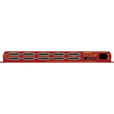
The RB-FS82 supports any configuration of up to 8 main program signal paths (N = 8) and there are 2 standby program signal paths, in either modes of operation. Each program path simultaneously switches analogue L/R audio, AES/EBU digital audio and RS232 data. Each of these signals is wired on D-type connectors on the rear panel. All signal paths are passive and therefore completely transparent utilizing relay based switching. This has the benefit of a "straight wire" topology during normal (alarm free) operation and also during any power outage to the device. An additional benefit of the passive signal path is AES/EBU bit transparency allowing throughput of AES/EBU AC3 Dolby E (TM) signals.
To ensure the passive nature of the device, switching is determined by alarm (General Purpose) inputs, with this alarm signaling in turn being normally provided by the encoder or decoders (or other devices) at site. Recognizing the mission critical nature of the system, a high grade of relay is used in the RB-FS82. The passive design ensures continuity of audio in the event of any power outage. However the RB-FS82 also includes dual redundant power supplies. This means that if either power supply fails, the other is ready to take over. In the extremely unlikely event that both fail, the unit's passive signal path ensures a straight wire connection for all 8 program feeds (analogue, AES/EBU & RS232). This is essential for applications such as installation at transmitter sites, where a power failure to the unit will not prevent the audio input signal from being output to each of the supported 8 transmitters.
A row of LEDs on the front panel confirm the unit status, with each individual program path indicated as being in alarm with either Standby 1 or Standby 2 programs clearly confirmed as actively over-riding the failed signal. Alarm LEDs on the front panel are also indicated for power supply 1 failure and power supply 2 failure and these are also mirrored by the device's own General Purpose Outputs so facilitating easy interfacing of the device with the addition of a summary alarm status GPO. In the event of alarm clearing, the unit will automatically revert to normal operation, but a manual reversion mode is also provided, allowing for engineering investigation without the unit 'hunting' between different signal paths. Two buttons on the front panel, RESTORE 1 and RESTORE 2, allow manual restoration of the previously failed signal paths, away from Standby 1 and Standby 2 respectively and these can be remotely controlled over Ethernet.