
Orders placed during Passover Holiday (Wed 4/1 after 4PM ET – Thurs 4/9) will ship Fri 4/10. View our holiday shipping schedule.
This item is no longer available.
Review Summary
Accidents happen where life happens. Protect your favorite Adorama products and purchase a protection plan to stay covered from accidental damage, mechanical or electrical failure, and more.
If we can’t fix it, we’ll replace it at no additional cost.
Protect your product from drops, spills, and more.
Enjoy your gear without fear. We have you covered!
When regular use of your product over time results in mechanical or electrical failure.
We will never charge you a deductible after the purchase of a plan.
Our claims process is simple & easy and our customer service team is happy to help.
Adorama Protect powered by Extend is available for purchase to customers in the United States. Not available for purchase Internationally or in U.S. Territories.
Browse our FAQ
Input connector: 2x BNC, passive loopthrough
Input impedance: 75Ohm
Input signal: NTSC/PAL black burst or HDTV tri-level sync (720p, 1080i)
Amplitude range: Standard +/- 6dB
S/N ratio: >40dB
SCH phase: 0 +/-40 deg.
Return loss: =30dB at 5MHz to 30MHz
Burst lock / sync lock stability: +/-3dB amplitude change: <1 ns
Jitter with burst lock: <0.5 deg.
Jitter with sync lock: <1 ns
Input connector: 1x BNC, internally terminated
Input impedance: 75Ohm
Input signal: CW (continuous wave)
Amplitude: 2V (1 to 2.25) Vp-p
Frequency: NTSC/PAL FSC, 1/5/10MHz
Return loss: >30dB to 30MHz
Over the amplitude range (CW lock stability): <1 ns
Jitter (CW lock stability): <1 ns (typical 1 deg. ) with CW input S/N >50dB
Range: Anywhere in the color frame
Resolution: <0.5 deg. of NTSC/PAL subcarrier
1 ns with tri-level sync input
Color framing: Keeps accuracy even with +/- 45 deg. SCH error of input reference input
Output signal (Black 1): NTSC/PAL black burst output
Output signal (Black 2, 3): NTSC/PAL black burst output or tri-level HDTV sync
Output format: 3x NTSC/PAL black burst (one black burst is independent, 2 black burst are distributed outputs)
2x NTSC/PAL black burst, 1x HDTV tri-level sync (all three outputs are independent)
1x NTSC/PAL black burst, 2x HDTV tri-level sync (HDTV tri-level are distributed from the same source)
Output impedance: 75Ohm
Return loss: >30dB to 30MHz
Output standards: EBU N14, SMPTE RP154
PAL-M and PAL-N are not supported
Amplitude accuracy: Standard black burst +/-2%
Burst frequency: NTSC/PAL FSC +/-1Hz
SCH phase: < +/-5 deg.
Timing adjustment (Range): Anywhere in the color frame
Timing adjustment (Resolution): <0.5 deg. of NTSC/PAL subcarrier
Standards: SMPTE 240M, 274M, 296M, RP211
Formats: 1080i/50Hz, 59.94 Hz, 60Hz
1080p/23.98Hz, 24Hz, 25Hz, 29.97Hz, 30Hz
1080psF/23.98Hz, 24Hz
720p/59.94Hz, 60Hz
Amplitude accuracy: Standard HDTV tri-level +/-2%
Timing adjustment (Range): Anywhere in the frame
Timing adjustment (Resolution): <1 ns
Standards: ANSI S4.40 (AES3), AES3-ID
Output channels: 8 channels (4 AES/EBU pairs)
Output impedance: 75Ohm, unbalanced
Output connector: 4x BNC
Output amplitude: 1V +/-0.2V
Frequency (Hz): 50, 100, 150, 200, 250, 300, 400, 500, 600, 750, 800, 1000, 1200, 1500, 1600, 2000, 2400, 3000, 3200, 4000, 4800, 5000, 6000, 8000, 9600, 10000, 12000, 15000, 16000, 20000Hz
Level: -60 to 0 dBFS, 1dB step
Sampling frequency: 48kHz (lock on video signal)
Quantization: Linear PCM, 20 or 24 bits (2's complement)
Transfer coding: Bi-phase mark
Standards: ANSI S4.40 (AES3), AES3-ID
Channel: 2 channels (1 AES/EBU pair)
Output impedance: 75Ohm, unbalanced
Output connector: 1x BNC
Output amplitude: 1 +/-0.2V
Frequency, level: No signal
Sampling frequency: 48kHz (lock on video signal)
Quantization: Linear PCM, 20 or 24 s (2's complement)
Transfer coding: Bi-phase mark
Output connector: 1x BNC
Output level: CMOS compatible
Frequency: 48kHz
Output signal (preinstalled for all formats): 100%, 75% andSMPTE Color Bars, Linearity, Flat Field, Multiburst, Sweep, Monitor, Pulse & Bar and other major test signals
ID text: Max 18 characters; one row (character 14x11 pixels)
Text and Position is embedded to each signal
Luminance amplitude: +/-1% (measured at 700mV)
Chrominance-to-luminance gain: +/-1%
Frequency response: +/-1% to 5.5MHz
Chrominance-to-luminance delay: =10 ns
Linearity: =1% (measured at 5 step signal)
Differential gain error: =0.5%
Differential phase error: =0.5 deg.
NTSC/NTSC no setup signals: 100%/75% Color Bars, SMPTE Color Bars, 40% Flat Field, Black Burst, Black Burst with Field REF, Monitor Setup, SNG ColorBars
PAL signals: 100%/75% Color Bars, 100%/75% Color Bars over RED, 40% Flat Field, Black Burst, Black Burst with No Field REF, Monitor Setup, SNG Color Bars
ID text: Max 18 characters; one row (character 14x11 pixels)
Text and Position is embedded to each signal
Luminance amplitude: +/-1% (measured at 700mV)
Chrominance-to-luminance gain: +/-2%
NTSC/NTSC no setup signals: Black Burst, Black Burst with Field Reference, Subcarrier, Composite Sync, H Drive, V Drive, Composite Blanking andColorFrame ID
PAL signals: Black Burst, Black Burst with Field Reference, Subcarrier, Composite Sync, H Drive, V Drive, Composite Blanking, Color FrameID and PAL Pulse
Timing pulse amplitude: -0.5 to 0.5 V (1 Vp-p)
Standards: ITU-R BT.470-6 (PAL-M and PAL-N are not supported)
SMPTE 170M
Output impedance: 75Ohm
Return loss: =36dB to 6MHz
Burst amplitude: +/-2%
Sync amplitude: +/-2%
Blanking level: 0 mV +/-50 mV
SCH phase accuracy: 0 deg. +/-5 deg.
Timing offset range: Full color frame
Timing offset resolution: 54 MHz clock resolution
Test signals: Output signal (preinstalled for all formats): 100%, 75% andSMPTE Color Bars, Linearity, Flat Field, Multiburst, Sweep, Monitor, Pulse & Bar and other major test signals
Formats supported: NTSC, NTSC No Setup, PAL, 525 R'G'B', 525 Y'P'bP'r, 525 Beta, 625 R'G'B', 625 Y'P'bP'r
Output connector: 6x BNC
Outputs: 6 identical analog composite outputs, 2 identical component video outs, or 2 identical Y/C and composite out
Output impedance: 75Ohm
Luminance linearity error: =0.5%
Luminance amplitude: +/-1% (measured at 700mV)
Chrominance-to-luminance gain error: =1% (relative to 100kHz)
Chrominance-to-luminance delay: =2.5 ns on a composite output (typical)
Channel-to-channel delay: =2 ns (relative to CH1)
Frequency response: =0.5% to 8MHz at 700mV (typical)
Differential gain error: =0.5%
Differential phase error: =0.5 deg.
Timing adjustment (Range): Anywhere in the frame
Timing adjustment (Resolution): 0.1 ns
Return loss: =40dB to 6MHz
Test signals: (Preinstalled for all formats) 100%, 75% andSMPTE Color Bars, Linearity, Multiburst, Sweep, Monitor and other major test signals
Formats supported: (All formats are factory preinstalled)
Y'P'bP'r or R'G'B' 1080i/50Hz, 59.94Hz, 60Hz
1080p/23.98Hz, 24Hz, 25Hz, 29.97Hz, 30Hz
1080psF/23.98Hz, 24Hz
720p/23.98Hz, 24Hz, 25Hz, 29.97Hz, 30Hz, 50Hz, 59.94Hz, 60Hz
Output connector: 6x BNC
Outputs: 2 identical analog component video outputs
Output impedance: 75Ohm
Output amplitude: =1% at 700mV
Channel-to-channel delay: =2 ns (relative to CH1)
Frequency response: +/-1% to 20MHz, +/-2% to 28MHz, +/-3% to 30MHz
Timing adjustment (Range): Anywhere in the frame
Timing adjustment (Resolution): 0.1 ns
Return loss: =35dB to 30MHz
Output connector: 4x BNC
Output impedance: 75Ohm
Output formats: NTSC/PAL black burst or HDTV tri-level sync, each output independently selectable
PAL-M and PAL-N are not supported
With Option CB, NTSC/PAL test signals are available on outputs 3 and 4
Return loss: =30dB to 30MHz
Jitter: =1 ns
Output standards: EBU N14, SMPTE RP 154, RP318M-B
Required hardware: V1.2 or above
Line: One or two lines, user selectable
Source: Time-of-day with adjustable offset, or program (elapsed) time counter
Amplitude accuracy: Standard black burst +/-2%
SCH phase: <+/-5 deg.
Timing adjustment (Range): Anywhere in the color frame
Timing adjustment (Resolution): Clock resolution 18.5 ns (1/54 Mus)
Standards: SMPTE 240M, 274M, 296M, RP211
Formats: 1080i/50Hz, 59.94Hz, 60Hz
1080p/23.98Hz, 24Hz, 25Hz, 29.97Hz, 30Hz
1080psF/23.98Hz, 24Hz
720p/50Hz, 59.94Hz, 60Hz
Amplitude accuracy: Standard HDTV tri-level +/-2%
Timing adjustment (Range): Anywhere in the frame
Timing adjustment (Resolution): Clock resolution 13.5 ns (1/74.25 Mus)
Test signals: (Preinstalled for all formats) 100%, 75% andSMPTE Color Bars, Linearity, Multiburst, Sweep, Monitor, SDI Pathological, Timing, and other major test signals
Standards: ITU-R BT 601, 656, EBU Tech 3267, SMPTE 125M, 244M, 259M, 272M, RP165, RP178
Bit rate: 143MBps, 270MBps (143MBps is only available when the module is installed in a TG700)
Resolution: 8 or 10 bits
Output connector: 2x or 4x BNC with Option B
Output impedance: 75Ohm
Output amplitude: 800 mVp-p +/-10%
Overshoot: =10%
Rise/fall time: 0.4 to 1.5 ns (20-80%)
DC offset (AC couple): 0 +/-0.5V
Jitter: =0.2 UI, above 10Hz jitter frequency
Timing adjustment (Range): Anywhere in the frame
Timing adjustment (Resolution): Clock resolution (37 or 70 ns)
Return loss: >15dB at 5-270MHz
Active channels: 1-16 channels
Sample frequency: 48kHz
Digital coding: 20 or 24 bits
Signal alignment: Asynchronous and Synchronous (no frame #), Synchronous (frame #)
Audio tone frequency: 50, 100, 150, 200, 250, 300, 400, 500, 600, 750, 800, 1000, 1200, 1500, 1600, 2000, 2400, 3000, 3200, 4000, 4800, 5000, 6000, 8000, 9600, 10000, 12000, 15000, 16000, 20000Hz
Level: -60 to 0 dBFS, 1dB steps
Type: L1 frequency (1575.42MHz), C/A Code, 12 channels
Time of day: User-selectable time zone and DST offset adjustment
Connector: BNC
Input impedance: 50Ohm, internally terminated
DC antenna power output voltage: 3.3V or 5V at nominal load
Fault protection: Short-circuit/open detection and protection
Return loss: 8dB at 1575MHz
Input connector: BNC, terminated, shared with BLACK 1 output
Input impedance: 75Ohm
Input signal: NTSC/PAL black burst or HDTV tri-level sync
Amplitude range: Standard -6dB to +8dB
S/N ratio: >40dB
SCH phase: 0 +/-40 deg.
Return loss: =30dB at 300kHz to 10MHz
Burst lock / sync lock stability: +/-3dB amplitude change: <1 ns
Jitter with burst lock: <0.5 deg.
Jitter with sync lock: <1 ns
Genlock time adjustment (Range): Anywhere in the color frame
Genlock time adjustment (Resolution): <0.5 deg. of NTSC/PAL subcarrier, 1 ns with tri-level sync input
Color framing: Keeps accuracy even with +/-45 deg. SCH error of input reference input
Time reference: VITC reader for NTSC/PAL black burst input signal
Output connector: 3x BNC
Output impedance: 75Ohm
Output formats: NTSC/PAL black burst or HDTV tri-level sync, each output independently selectable
PAL-M and PAL-N are not supported
Black output 3 can be configured as a 10 MHz continuous wave output
Return loss: =30dB to 30MHz
Output standards: EBU N14, SMPTE RP 154, RP318M-B
Line: One or two lines, user selectable
Source: Time-of-day with adjustable offset, or program (elapsed) time counter
Amplitude accuracy: Standard black burst +/-2%
SCH phase: < +/-5 deg.
Timing adjustment: Each output is independent
Range: Anywhere in the color frame
Resolution: Clock resolution 18.5 ns (1/54 Mus)
Standards: SMPTE 240M, 274M, 296M, RP211
Formats: 1080i/50Hz, 59.94Hz, 60Hz
1080p/23.98Hz, 24Hz, 25Hz, 29.97Hz, 30Hz
1080psF/23.98Hz, 24Hz
720p/59.94Hz, 60Hz
Amplitude accuracy: Standard HDTV tri-level +/-2%
Timing adjustment: Each output is independent
Range: Anywhere in the color frame
Timing adjustment (Resolution): Clock resolution 13.5 ns (1/74.25 Mus)
LTC1 can be configured as an input, a time-of-day source, or an output
23.98, 24, 25, 30 fps drop-frame as per SMPTE 12M
Compliant with SMPTE 12M and continues to operate over at least 90% of possible timing range
0.5 to 10 Vp-p differential, 1 to 5 Vp-p single ended
-30dB SNR RMS white noise with 10kHz BW to the p-p signal level, or -10dB SNR for 5MHz white noise
0dB hum-to-signal ratio
100 consecutive frames with consistent time code must be detected for time to be considered valid
Nominal 600Ohm differential, 300Ohm single ended
4 independent
Available through D-sub 15-pin connector
24 fps (24Hz or 23.98Hz), 25 fps, 30 fps, 30 fps drop-frame as per SMPTE 12M
Time-of-day with adjustable offset, or program (elapsed) time counter
5V +/-10%; adjustable from 0.5V to 5V in 0.5V steps
Server only, using Ethernet interface on the TG8000 mainframe
NTPv3 for IPv4, per RFC 2030
Available through D-sub 15-pin connector
Two, user-selectable to assert when GPS synchronization is lost, GPS signal falls below threshold, or elapsed time value reaches set value
In Genlock mode, user-selectable to assert on loss-of-lock or near loss-of-lock
0.5-5V
One, user-selectable to signal GPS reacquisition or restart timer
0.8-2.4V
Test signals: (Preinstalled for all formats) 100%, 75% andSMPTE Color Bars, Linearity, Multiburst, Sweep, Monitor, SDI Pathological, Timing and other major test signals
Standards: SMPTE 240M, 272M, 274M, 292, 296M
Bit rate: 1.485GBps, 1.485/1.001GBps
Output formats: 1035i/59.94Hz, 60Hz
1080i/50Hz, 59.94Hz, 60Hz
1080p/23.98Hz, 24Hz, 25Hz, 29.97Hz, 30Hz
1080psF/23.98Hz, 24Hz
720p/23.98Hz, 24Hz, 50Hz, 59.94Hz, 60Hz
Required Hardware: V2.0 or above
Source: Time-of-day with adjustable offset, or program (elapsed) time counter
Output connector: 2x or 4x BNC with Option BK
Output impedance: 75Ohm
Output amplitude: 800 mVp-p +/-10% (typical)
Overshoot: =10% (typical)
Rise/fall time: =270 ps (20-80%) (typical)
DC offset (AC coupling): 0V +/-0.5V (typical)
Jitter: =135 ps (typical) alignment
Timing adjustment (Range): Anywhere in the frame
Timing adjustment (Resolution): Clock resolution 13.5 ns (1/74.25MHz)
Return loss: =15dB from 5MHz to 750MHz
=10dB from 750MHz to 1.485GHz (typical)
Active channels: 1-16 channels
Sample frequency: 48kHz
Digital coding: 20 or 24 bits
Signal alignment: Asynchronous and Synchronous (no frame #), Synchronous (frame #)
Audio tone frequency: 50, 100, 150, 200, 250, 300, 400, 500, 600, 750, 800, 1000, 1200, 1500, 1600, 2000, 2400, 3000, 3200, 4000, 4800, 5000, 6000, 8000, 9600, 10000, 12000, 15000, 16000, 20000Hz
Level: -60 to 0 dBFS, 1dB steps
Test signals: 100%, 75% andSMPTE Color Bars, Flat Field (0% to 100% in 10% steps), 100% and 75% Red/Green/Blue, Convergence, Ramp, Valid Ramp, 5-step Staircase, 2T30 Pulse and Bar, SDI Pathological
Projector test patterns (2K only): Color Patch 1, Color Patch 2, Black-to-White Step Scale, Black-to-Gray Step Scale, Horizontal Gradient, Vertical Gradient, Flat Fields (each step-scale color), Red/Green/Blue/Cyan/Magenta/Yellow Color Fields, Grid, Aspect Ratio Frame, Checkerboard, Window
HD-SDI converter: Input signal up-converted to dual link format for output signal
Standards: SMPTE 372M, 292, 274M, 352M
Bit rate: 1.485GBps, 1.485/1.001GBps for each link
Output formats: 1080i/50Hz, 59.94Hz, 60Hz
1080p/23.98Hz, 24Hz, 25Hz, 29.97Hz, 30Hz, 50Hz, 59.94Hz, 60Hz
1080psF/23.98Hz, 24Hz
2048x1080p/23.98Hz, 24Hz, 25Hz, 29.97Hz, 30Hz
2048x1080psF/23.98Hz, 24Hz
2048x1556psF/14.99Hz, 15Hz, 17.98Hz, 18Hz
Sampling formats: 4:2:2 Y'C'bC'r, 4:4:4 Y'C'bC'r, 4:4:4 G'B'R', 4:4:4 X'Y'Z'
Word size: 10 or 12 bits
Alpha channel: Same as Y/G channel or Flat Field (0% to 100% in 10% steps)
Embedded audio: 16 channels copied from input signal to Link A and/or Link B in convertor mode; no embedded audio in Generator mode
Payload identifier: Link A and Link B identified as per SMPTE 352M
Link timing offset: Adjustable timing offset between Link A and Link B, +/-200 ns in single clock increments
Output impedance: 75Ohm
Output amplitude: 800 mVp-p +/-10%
Overshoot: =10% (typical)
Rise/fall time: =270 ps (20-80%)
DC offset (AC coupling): 0V +/- 0.5V (typical)
Jitter: =135 ps (typical) alignment
Timing adjustment (Range): Anywhere in the frame
Timing adjustment (Resolution): Clock resolution 13.5 ns (1/74.25MHz)
Return loss: =15dB from 5MHz to 750MHz
=10dB from 750MHz to 1.485GHz
Test signals: 100%/75%/SMPTE (EG1, EG432-1, RP219) Color Bars, 0%/50%/100% Flat field, Red/Green/Blue/Cyan/Magenta/Yellow 100% Field, Ramp, Limit Ramp, Valid Ramp, Shallow Ramp Matrix, 5/10 Step Staircase, Checkerboard, Clean Aperture, Convergence, Black-White Step Scale, Black-Dark Gray Step Scale, Pluge and Luma Reference, Production Aperture, Window, SMPTE 303M Color Reference
ChromaDuMonde, 2T Pulse and Bar, Color Pulses, Equalizer Test, PLL Test, SDI Matrix, Co-siting Pulse, Parametric Moving Zone Plate (More test signals are available on the TG8000 SW Library and Documentation DVD)
HD-SDI converter: Input 1080 line HD-SDI signal up-converted to output 3G-SDI signal
Standards: SMPTE 12M-2, 272M, 274M, 291M, 292M, 296M, 299M, 352M, 424M, 425M-AB
Bit rate: 2.97GBps, 2.97/1.001GBps, 1.485GBps, 1.485/1.001 GBps
Output formats: 720p/23.98Hz, 24Hz, 25Hz, 29.97Hz, 30Hz, 50Hz, 59.94Hz, 60Hz
1080i/50Hz, 59.94Hz, 60Hz
1080p/23.98Hz, 24Hz, 25Hz, 29.97Hz, 30Hz, 50Hz, 59.94Hz, 60Hz
1080psF/23.98Hz, 24Hz, 25Hz, 29.97Hz, 30Hz
2048x1080p/23.98Hz, 24Hz, 25Hz, 29.97Hz, 30Hz
2048x1080psF/23.98Hz, 24Hz, 25Hz, 29.97Hz, 30Hz
Sampling formats: 4:2:2 Y'C'bC'r, 4:2:2 Y'Cb'Cr'+A, 4:4:4 Y'Cb'Cr', 4:4:4 Y'C'bC'r+A, 4:4:4 G'B'R', 4:4:4 G'B'R'+A, 4:4:4 X'Y'Z'
Word size: 10 or 12 bits
3G-SDI mapping formats: Level A, Level B, 2x HD in Level B
Alpha channel: Same as Y/G channel or Flat Field (0% to 100% in 10% steps)
Payload identifier: Per SMPTE 352M
Source: Time-of-day with adjustable offset (if GPS7 module is present), or program (elapsed) time counter
Ancillary data: User programmable
Content: DID, SDID, DC, UDW (255), CS. Automatically calculate checksum and/or parity, or manual override
Location: Line number, sample offset, luma/chroma channel, virtual link
Mode: Continuous insertion or single packet
Output impedance: 75Ohm
Output amplitude: 800 mVp-p +/-3%
Overshoot: =5% (typical)
Rise/fall time: =135 ps (20-80%)
DC offset (AC coupling): 0 V +/-0.5V (typical)
Jitter: =67 ps (typical) (3 Gb, alignment)
=80 ps (typical) (3 Gb, timing)
Timing adjustment (Range): Anywhere in the frame
Timing adjustment (Resolution): One clock cycle at the Y, G, or X pixel rate
Return loss: =15dB from 5MHz to 2.5GHz
=10dB from 2.5GHz to 3GHz
Active channels: 1-32 channels
Sample frequency: 48kHz
Digital coding: 24 bits
Signal alignment: Asynchronous and Synchronous (no frame #), Synchronous (frame #)
Audio tone: 10Hz to 20000Hz, 0.5Hz resolution
Level: -60 to 0 dBFS, 1dB steps
Output format: 148.5MHz clock, frame pulse, or line pulse
Output impedance: 50Ohm
Output amplitude: 720 mVp-p +/-10%
Return loss: =15dB from 10MHz to 300MHz
Test signals: 100%/75%/SMPTE (EG1, EG432-1, RP219) Color Bars, 0%/50%/100% Flat field, Red/Green/Blue/Cyan/Magenta/Yellow 100%Field, Ramp, Limit Ramp, Valid Ramp, Shallow Ramp Matrix, 5/10 Step Staircase, Multiburst, Checkerboard, Clean Aperture, Convergence, Black-White Step Scale, Black-Dark Gray Step Scale, Pluge and Luma Reference, Production Aperture, Window,SMPTE 303M Color Reference
ChromaDuMonde, 2T Pulse and Bar, Color Pulses, Equalizer Test, PLL Test, SDI Matrix, Cositing Pulse, Parametric Moving Zone Plate (More test signals are available on the TG8000 SW Library and Documentation DVD)
Standards: SMPTE 12M-2, 259M, 272M, 274M, 291M, 292M, 296M, 299M, 352M, 424M, 425M-AB
Bit rate: 2.97GBps, 2.97/1.001GBps, 1.485GBps, 1.485/1.001GBps, 270MBps
Output formats: 525i/59.94Hz
625i/50Hz
720p/23.98Hz, 24Hz, 25Hz, 29.97Hz, 30Hz, 50Hz, 59.94Hz, 60Hz
1080i/50Hz, 59.94Hz, 60Hz
1080p/23.98Hz, 24Hz, 25Hz, 29.97Hz, 30Hz, 50Hz, 59.94Hz, 60Hz
1080psF/23.98Hz, 24Hz, 25Hz, 29.97Hz, 30Hz
2048x1080p/23.98Hz, 24Hz, 25Hz, 29.97Hz, 30Hz
2048x1080psF/23.98Hz, 24Hz, 25Hz, 29.97Hz, 30Hz
Sampling formats: 4:2:2 Y'C'bC'r, 4:2:2 Y'Cb'Cr'+A, 4:4:4 Y'Cb'Cr', 4:4:4 Y'C'bC'r+A, 4:4:4 G'B'R', 4:4:4 G'B'R'+A, 4:4:4 X'Y'Z'
Word size: 10 or 12 bits
3G-SDI mapping formats: Level A, Level B, 2x HD in Level B
Alpha channel: Same as Y/G channel or Flat Field (0% to 100% in 10% steps)
Payload identifier: Per SMPTE 352M
Source: Time-of-day with adjustable offset (if GPS7 module is present), or program (elapsed) time counter
Ancillary data: User programmable
Content: DID, SDID, DC, UDW (255), CS. Automatically calculate checksum and/or parity, or manual override
Location: Line number, sample offset, luma/chroma channel, virtual link
Mode: Continuous insertion or single packet
Full frame picture: Up to 1920x1080 (.bmp file)
Logo: Up to 1920x1080 (.bmp file)
Text: A preinstalled TrueType font is provided for Latin, Greek and Cyrillic characters; users may provide their own TrueType font to support other characters
Output impedance: 75Ohm
Output amplitude: 800 mVp-p +/-3%
Overshoot: =1% (typical)
Rise/fall time (HD, 3G): =70 ps (typical) (20-80%)
Rise/fall time (SD): =700 ps (typical) (20-80%)
DC offset (AC coupling): 0V +/-0.5V (typical)
Jitter (HD, 3G): =50 ps (typical) (alignment), =80 ps (typical) (timing)
Jitter (SD): =200 ps (typical) (alignment), =200 ps (typical) (timing)
Timing adjustment (Range): Anywhere in the frame
Timing Adjustment (Resolution): One clock cycle at the Y, G, or X pixel rate
Return loss: =15dB from 5MHz to 2.5GHz (typical)
=10dB from 2.5GHz to 3GHz (typical)
Active channels: 32 channels (3G-B)
16 channels (SD, HD, 3G-A)
Sample frequency: 48kHz
Digital coding: 24 bits (HD, 3G)
20 bits (SD)
Signal alignment: Asynchronous and Synchronous (no frame #)
Synchronous (frame #)
Audio tone: 10Hz to 20000Hz, 0.5Hz resolution
Level: -60 to 0 dBFS, 1dB steps
Output formats: System Clock, Pixel Clock, Line Rate Pulse, Field/Frame Rate Pulse
Output impedance: 50Ohm
Output amplitude: 520 mVp-p +/-10%
Return loss: =15dB from 10MHz to 300MHz (typical)
Internal mode: '+/-110 x 10-9 over 1-year calibration interval
Typically +/-10 x 10-9 just after adjustment
Over temperature: +/-2 x 10-9 for +/-5 deg. C variation
+/-10 x 10-9 for 0 to 50 deg. C
< +/-100 x 10-9 per year for internal and stay current frequency / stay genlock modes at constant temperature
+/-50 x 10-6
4
1
USB 2.0 on front panel
1000/100/10BASE-T on power supply module
GPIO interface for preset recall input, alarm output on power supply module
Sync pulse generator and test signal generator for post production and broadcast facilities
Test signal generator for research and development
Equipment design and maintenance
135W (maximum)
0 to 50 deg. C / 32 to 122 deg. F
4500m / 14763.60'
100-240V, 50/60Hz
44 x 483 x 559mm / 1.73 x 19.02 x 22.01"
6kg / 13.23lbs
The TG8000 is a precision multiformat analog and digital signal generation platform, designed for sync pulse and timecode generation in broadcasting applications and reference test signal generation in video equipment testing applications.
Multiformat analog and digital test signal generation
Ideal channel configuration and performance to support reference generator needs
Modular configurable platform
Stay GenLock - Unique, robust Genlock mode provides stable synchronization signals for digital and traditional broadcast facilities
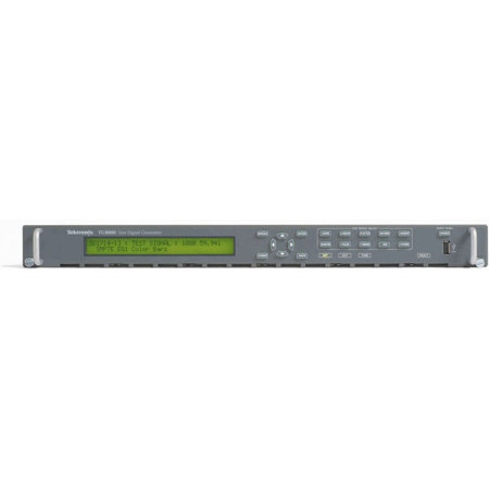
TG8000 Mainframe
The TG8000 mainframe is a modular system, accommodating up to four user-changeable generator modules and one power supply module in a full-width 1RU form factor. A total of 12 different modules are available for the TG8000, covering a wide range of interfaces and functions such as GPS synchronization and genlock, SD/HD/3G-SDI test signal generation, composite and component analog test signal generation and audio test signal generation.
The TG8000 mainframe has a high-precision oscillator for master operation or for stable holdover operation when the genlock or GPS reference is interrupted. A 10/100/1000 BASE-T Ethernet interface provides connectivity to the local network for remote operation, test pattern download and an NTP server (when the GPS7 module is present). A General Purpose Input/Output (GPIO) interface is available to recall one of seven user-configured presets and to report system alarms. The front-panel USB port can be used to easily download user-created test patterns and system preset information and can be used for system upgrades.
AGL7 Analog Genlock Module
The AGL7 Analog Genlock Module adds the capacity to lock to a variety of signals, which makes the TG8000 an ideal solution as the master house reference or slave reference for broadcast and production/post-production applications. Three black outputs are available and are selectable for HDTVtri-level or NTSC or PAL. Additionally, the AGL7 can lock to a variety of formats to include NTSC/PAL black and HDTV tri-level as well as 1, 3.58, 4.43, 5 and 10MHz CW. When the AGL7 is configured for Stay GenLock mode, a momentary loss of synchronization at the genlock reference input will not cause a disturbance in the TG8000 test signal and black outputs. When the genlock signal is reapplied, the AGL7 will gradually reacquire lock, causing little disruption to devices synchronized to the TG8000 reference.
GPS7 GPS Synchronization and Time Code Module
The GPS7 GPS Synchronization and Time Code Module includes an integrated GPS receiver which can serve as the system timing reference. Synchronization to the GPS timing signals ensures long-term stability and video frame alignment between independent systems. The GPS RF coaxial signal input is available with 3.3V or 5VDC power output for the GPS antenna enabling the user to select from a variety of GPS antennas available on the market. The GPS7 also includes a genlock input with VITC reader, enabling user-selectable configuration of the TG8000 as the master reference or as a slave to another master, depending on the dynamic requirements of each production.
The GPS7 module will maintain system timing by Stay GenLock technology even during periods of GPS signal loss or genlock signal loss. Three black outputs are available and are selectable for HDTV tri-level, NTSC or PAL. Time code source can be selectable to the time-of-day (with user-selectable offsets) from GPS receiver, internal source, VITC on the reference input, LTC input or to a ""program time"" counter for elapsed-time time code.
The Daylight Savings Time (DST) adjustment could be scheduled as a recurring event based on calendar rules. Time code is available as VITC on black outputs (GPS7, BG7 - hardware V1.2 or above), as Ancillary Time Code (ATC) (HDVG7 - hardware V2.0 or above, HD3G7, SDI7), from four independent LTC outputs (GPS7) and as a response to time requests on a Network Time Protocol (NTP version 3.0) Server.
ATG7 Composite Analog Test Generator Module
The ATG7 Composite Analog Test Generator Module supports PAL, NTSC and NTSC No Setup. It provides one test signal output, one color bar test signal output and two black outputs. The black outputs can independently generate H, V, black burst and subcarrier.
AVG7 Analog Video Generator Module
The AVG7 Analog Video Generator Module outputs 525/625 interlace formats supporting component (Y'P'bP'r, G,B,R, Y/C), 525 Beta and composite (PAL, NTSC, NTSC No Setup). The module provides two identical component outputs, two identical Y/C and composite or six identical composite outputs.
AWVG7 Analog Wideband Video Generator Module
The AWVG7 Analog Wideband Video Generator Module supports a variety of HD analog component formats (Y'P'bP'r or GBR). The module provides two identical component outputs with a bandwidth of 30MHz. Up to two AWVG7 modules can be placed in a single TG8000 mainframe.
AG7 Audio Generator Module
The AG7 Audio Generator Module provides eight channels (4 AES/EBU pairs) of audio signal generation. The module also provides two channels (1 AES/EBU pair) of silence as well as a 48kHz word clock output.
BG7 Analog Black Generator Module
The BG7 Analog Black Generator Module provides four independently selectable outputs. The module supports NTSC and PAL black burst as well as HDTV tri-level sync. With Option CB, two of the outputs can also generate various analog NTSC and PAL color bar test signals.
DVG7 SD-SDI Digital Video Generator Module
The DVG7 Digital Video Generator Module is a multi-format SD-SDI test signal generator supporting 525 line and 625 line serial digital video at 270 Mb/s. The module has two identical test signal outputs. With Option BK, two additional identical serial digital black signal outputs are available.
HDVG7 HD-SDI Digital Video Generator Module
The HDVG7 HD-SDI Digital Video Generator Module is a high-accuracy, multi-format, high-definition test signal module that provides up to two identical 1.485 Gb/s serial digital video test signal outputs in a broad variety of formats. With Option BK, two additional identical serial black signal outputs are available. Ancillary Time Code (ATC) generation is available when the GPS7 is installed in the TG8000 mainframe. Up to two HDVG7 modules can be placed in a single TG8000 mainframe.
The digital modules DVG7, HDVG7 and SDI7 support AV timing mode and up to 16 channels of 20- or 24-bit audio sampled at 48kHz embedded on the test signal outputs. The user can independently set frequency and level for each channel. Full frame test and custom patterns can be generated for the AVG7, AWVG7, DVG7, HDVG7 and SDI7 modules. Simple full frame patterns are available on the TG8000 CD-ROM.
HDLG7 Dual Link HD-SDI Generator Module
The HDLG7 Dual Link HD-SDI Generator Module is a test signal generator that provides two identical dual-link high-definition serial digital interface (HD SDI) outputs. The module supports video formats that require the use of a dual-link interface, such as 4:4:4 R'G'B' at rates up to 1080i/60Hz or 1080p/30Hz or 4:2:2: Y'C'bC'r at rates up to 1080p/60Hz. The HDLG7 supports several standard test signals and also has an ability to up-convert an arbitrary single-link HD-SDI input signal to a dual-link format for the outputs. The HDLG7 also supports digital cinema 2K formats and test patterns.
HD3G7 HD/3G-SDI Test Signal Generator Module
The HD3G7 HD/3G-SDI Test Signal Generator Module is a test signal generator that provides two outputs of a HD/3G-SDI video test signal. 720- line formats and 1080-line formats described in SMPTE standards are supported for both Level A and Level B mapping structures, including 4:4:4 and/or 12-bit sampling, Y'C'bC'r, R'G'B' or XYZ color space and 2K digital cinema formats. The 2XSMPTE 292M HD-SDI format used by some 3D TV applications is also supported.
The HD3G7 can generate up to 32 channels of 24-bit 48kHz embedded audio, with independently set frequency and amplitude for each channel. The HD3G7 also has the ability to generate other types of ancillary data, such as video payload identifier, ancillary time code and user-defined packets. The HD3G7 includes a wide variety of standard test signals, including SMPTE color bars, pathological test patterns and a programmable moving zone plate pattern and it also has the ability to up-convert an input 1.485Gbps HD-SDI signal to a 3G output. The module has a clock/frame trigger output that can be used to synchronize the output with an oscilloscope.
SDI7 SD/HD/3G-SDI Test Signal Generator Module
The SDI7 SD/HD/3G-SDI Test Signal Generator Module provides two independent channels of SD/HD/3G-SDI video test signal generation in a variety of formats with separate test and test/black signal generation per channel (3G-SDI signal generation is optionally available). The SDI7 can generate up to 32 channels of 24-bit 48kHz embedded audio, with independently set frequency and amplitude for each channel. Option DBT extends the audio functionality by generating these test tones in Dolby E format. Various Dolby E audio frame start locations can be set to test the error handling ability of the signal processing equipment in the signal path. Embedded Dolby E metadata are also included in the Dolby E test stream. Supported Dolby E program configurations include mono, stereo, 5.1 and 7.1 surround sound audio. The SDI7 also has the ability to generate other types of ancillary data, such as video payload identifier, ancillary time code and user-defined packets.