


+3
more
more
Picture does not represent the actual item
Picture does not represent the actual item
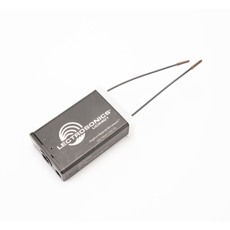
The UCR401 is a high performance compact UHF wireless microphone receiver for mobile applications such as ENG and film production. The compact size, battery and external power and rugged attached antennas are ideal for video camera mounted use. Unique DSP algorithms in the design provide full compatibility with all Lectrosonics 400 Series Digital Hybrid Wireless transmitters and variety of analog transmitters from Lectrosonics and some other manufacturers.
Power is provided by two AA batteries, typically NiMH rechargeable types or external DC supplied via a jack on the rear panel. Microprocessor control enables SmartSquelch and SmartDiversity advanced reception techniques to minimize noise and dropouts in all conditions. The receiver differentiates between close and distant operation and adjusts the squelch threshold automatically. In environments with significant RF reflections, the diversity switching activity optimizes the antenna combining based upon an analysis of RF level and audio content.
Finding a clear operating channel is simplified with a choice of 256 frequencies across a 25.6MHz bandwidth. A built-in RF spectrum analyzer scans the entire tuning range of the receiver and displays RF activity on the built-in LCD. Signal strength of other signals in the vicinity is indicated and empty sections of the spectrum are quickly identified with the graphical display. The analyzer will scan the entire spectrum and display the results in about 25 seconds, so it is easy to find a clear frequency in each new location.
The DSP generates a unique pilot tone frequency for each selected operating frequency to simplify coordination in multi-channel wireless systems. This eliminates the possibility of a valid pilot tone signal being passed to another receiver via IM (intermodulation) products. The balanced audio output is adjustable from -50 to +5 dBu in 1dB steps for an accurate match into the camera, mixer or recorder.
The LCD provides continuous displays of RF and audio levels, limiting in the transmitter when it occurs and battery status in both transmitter and receiver when used with Digital Hybrid transmitters. The simple 3-button interface allows quick navigation through a variety of menus and screens for setup and adjustment. The display will flash a warning as alkaline and lithium battery life nears the end and show a clock when set for a timer mode with rechargeable batteries.
Digital Hybrid Wireless
Digital Hybrid Wireless is a revolutionary design that combines digital audio with an analog FM radio link to provide both outstanding audio quality and exemplary, noise-free RF performance. Using a patented algorithm to encode 24-bit digital audio information in the transmitter into an analog format, the encoded signal is then transmitted over an analog FM wireless link. At the receiver, the signal is then decoded to restore the original digital audio. This process eliminates compandor artifacts and produces an audio frequency response flat to 20 kHz.
SmartSquelch
Conventional squelch design faces several compromises:
• Squelch too aggressively and audio may be lost
• Squelch too little and excessive noise may be heard
• Respond too rapidly and the audio will be "choppy"
• Respond too sluggishly and entire words or syllables can be cut off
SmartSquelch overcomes these problems by:
• Waiting for a complete word or syllable before squelching
• Assessing recent squelching history, RF level and the rate of change of RF level
• Assessing audio content to determine available masking
By adjusting squelching behavior dynamically under varying conditions, the UCR401 delivers acceptable audio quality from otherwise unusable signals.
SmartDiversity
SmartDiversity analyzes both the incoming RF level and the RF level's rate of change to determine the optimum timing for phase switching and the optimum antenna phase. This adaptive technique operates over a wide range of RF levels to anticipate dropouts before they occur. The system also employs "opportunistic switching" to analyze and then latch the phase in the best position during brief squelch activity.
SmartNR
In order to increase the effective dynamic range of the system, the UCR401 is equipped with a Smart Noise Reduction algorithm, which removes hiss without sacrificing high frequency response. SmartNR works by attenuating only those portions of the audio signal that fit a statistical profile for randomness or "electronic hiss." SmartNR offers significantly increased transparency over the sophisticated variable low pass filters used in previous designs. Desirable high frequency signals having some coherence such as speech sibilance and tones are not affected.
DSP-based Pilot Tone
The 400 Series system design uses a DSP generated ultrasonic pilot tone to control the receiver audio muting (squelch). By sensing the pilot tone and incorporating brief delays when the matching transmitter is turned on or off, thumps, pops and other transients are successfully eliminated. The pilot tone frequency is different for each of the 256 frequencies in the tuning range (frequency block) of a system, which simplifies the coordination of multichannel wireless systems. The DSP generated pilot tone system also eliminates fragile crystals, allowing the receiver to survive shocks and mishandling much better than older analog-based pilot tone systems.
Compatibility Modes
The UCR401 receiver is designed to operate with Lectrosonics 400 Series transmitters and will yield the best performance when doing so. However, thanks to the flexibility of digital signal processing, the UCR401 can also be used with Lectrosonics IFB, 200 and 100 Series and certain non-Lectrosonics analog transmitters in special compatibility modes.
Digital Hybrid Wireless Architecture
The block diagram below outlines the architecture of this Digital Hybrid Wireless receiver, starting with the frontend filter and ending with a balanced output. Front-end filters block high powered RF energy on nearby frequencies to protect the receiver from interference from sources like television broadcasts. After this filtering the signal is converted to the final 300 kHz IF frequency through three stages. A digital pulse counting detector recovers the encoded analog signal sent from the transmitter. This signal is then filtered, converted into a digital bit stream and sent to the DSP. The DSP then recovers the 24-bit digital audio signal that was generated in the transmitter, which is then converted to analog and delivered to the output stage.
Front Panel and LCD interface
Graphical icons indicate the status of all aspects of operation, including RF and audio levels, diversity switching activity and the status of batteries in the receiver and the transmitter being operated. Sub-menus and a variety of screens provide access to all settings and adjustments. The LCD is backlit for visibility in dim lighting conditions and remains very visible in direct sunlight. All menus and screens are accessed with three buttons on the front panel.
RF Spectrum Analyzer
The RF spectrum for UHF wireless microphones and IFB equipment has become increasingly crowded, due largely to the roll out of digital television broadcasts and the re-allocation of some spectrum for other services. More than ever, it is critically important to be able to find clear operating frequencies wherever a wireless system is going to operate. A built-in RF spectrum analyzer in the UCR401 addresses this situation. An RF site scan and analysis can be conducted in less than a minute using the LCD interface.
Simply pressing all three white buttons on the control panel sets the receiver into a scanning mode that sweeps the entire tuning range of the receiver in just over 20 seconds. The results of the scan are graphically displayed on the LCD showing the position and strength of RF signals detected and the clear sections of the spectrum. A marker in the display is scrolled to an area where there is no activity and the three buttons are pressed again.
A message appears prompting the choice of the new frequency selected by scrolling or the return to the previous frequency in place before the scan. When the frequency is selected, the display changes to a screen showing the selected frequency and the switch settings used on some transmitter models. The transmitter is set to the frequency and the system is ready for operation. Using the receiver itself to conduct a site scan is especially beneficial because any RF signals that are the product of IM (intermodulation) that occurs inside the receiver will also be displayed. An external spectrum analyzer can accurately identify RF signals outside of the receiver but it will not include IM products.
A Rugged, Practical Package
The receiver is powered by two AA batteries or from an external DC source via a locking connector. NiMH rechargeable batteries are economical and especially effective because they provide extended operating time, which is consistent with continuous or intermittent use. Audio is delivered via a balanced XLR connector, adjustable from mic to line level in 1 dB steps with the LCD interface on the front panel. A machined aluminum housing and battery door are designed for heavy use in field production. The battery door remains attached to the housing when opened.


