
Lectrosonics UCR411A Compact Digital Hybrid Wireless Tracking Receiver, Block 470: 470.100 - 495.600MHz
SKU: LEUCR411A470
This item is no longer available.
Recommended Alternatives
Share:
Overview
Compare
Specs
Protection
About Lectrosonics UCR411A
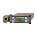
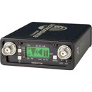
The UCR411A receiver provides professional performance and a versatile feature set in a compact design for field and location production. All settings are made from the front panel with a powerful LCD interface, making the unit ideal for use in portable bag systems, on sound carts and in rack mount multi-couplers. An RF spectrum analyzer is built into the receiver to alleviate interference problems in an increasingly congested RF spectrum.
The receiver tunes across its 25.6 MHz tuning range and records RF activity with markers on the LCD screen. Finding clear operating frequencies is a quick, simple process. The mechanical design of the receiver combines field proven features developed over many years of experience in motion picture and television production markets. The machined aluminum housing and panels are surfaced with electrostatic powder coated and anodized finishes with laser etched markings to withstand the rigors of field production.
DSP Compatibility Modes
The native, compandor-free Digital Hybrid operating mode works with all Lectrosonics hybrid transmitters. DSP "compatibility modes" allow the receiver to also work with companded analog transmitters from Lectrosonics and some from other manufacturers. This expands the usefulness of the receiver and provides the backward compatibility needed to give existing customers an economical upgrade path.
Frequency Tracking Front-End Filters
The front-end consists of four transmission line resonators with variable capacitance applied to each resonator to retune it as the frequency is changed. The tuning range covers a full 25.6 MHz block of frequencies. The design provides tunable, narrow filtering as selective as most fixed frequency designs, with the overload performance of the best front-ends available. The result is extended operating range in even the most congested RF environments.
Digital Hybrid Wireless
Digital Hybrid Wireless technology is a revolutionary new design that combines digital audio with an analog FM radio link to provide outstanding audio quality and the exemplary RF performance of the finest analog wireless systems. The design overcomes channel noise in a dramatically new way, digitally encoding the audio in the transmitter and decoding it in the receiver, yet still sending the encoded information via an analog FM wireless link.
This proprietary algorithm is not a digital implementation of an analog compandor. Instead, it is a technique which can be accomplished only in the digital domain. The process eliminates a compandor and its artifacts, expanding the applications to include test and measurement of acoustic spaces and musical instruments.
SmartSquelch
Conventional squelch design faces several compromises:
• Squelch too aggressively and audio may be lost
• Squelch too little and excessive noise may be heard
• Respond too rapidly and the audio will sound "choppy"
• Respond too sluggishly and entire words or syllables can be cut off
SmartSquelch achieves an optimal balance of these tradeoffs by combining several techniques that remove distracting noise without the squelching action itself becoming a distraction. The circuitry will perform the following functions:
• Wait for a complete word or syllable before squelching
• Assess recent squelching history and RF signal strength
• Assess audio content to determine available masking
By adjusting squelching behavior dynamically for the optimal result under varying conditions, the receiver can deliver acceptable audio quality from otherwise unusable signals.
SmartDiversity
Microprocessor controlled antenna phase combining is utilized for diversity reception to keep the receiver small, yet still deal effectively with multi-path dropouts. The embedded firmware analyzes RF level, the rate of change of RF level and the audio content to determine the optimum timing for phase switching and the optimum antenna phase. This adaptive technique operates over a wide range of RF levels to anticipate dropouts before they occur. The system also employs "opportunistic switching" to analyze and then latch the phase in the best position during brief squelch activity.
SmartNR
With a noise floor at -120 dBV and a frequency response to 20 kHz, high frequency noise in the source audio is more apparent than in conventional wireless systems. The Smart Noise Reduction algorithm works by attenuating only those portions of the audio signal that fit a statistical profile for randomness or "electronic hiss." Because it isn't simply a sophisticated variable low pass filter as in earlier analog designs, much greater transparency is obtained. Desired high frequency signals having some coherence such as speech sibilance and tones are not affected.
The Smart NR algorithm has three modes, selectable from the front panel LCD. When switched OFF, no noise reduction is performed. When switched to NORMAL, the factory default setting, enough noise reduction is applied to remove most of the hiss from the mic preamp and some of the hiss from lavaliere microphones. When switched to FULL, enough noise reduction is applied to remove most of the hiss from nearly any signal source of reasonable quality, assuming levels are set correctly at the transmitter.
Analog RF Links
A digitized audio or RF signal occupies a good deal more bandwidth than the original analog signal. A digital transmission over the air requires some combination of additional power, more RF bandwidth and/or compression of the audio data to achieve adequate operating range and keep the energy inside the defined spectral mask. Because of this, digital wireless microphones typically lack the operating range of conventional FM systems. With regard to using RF power and spectrum efficiently, an analog RF link has many advantages in wireless mic systems, among them long battery life, excellent range and the ability to use many systems in close proximity without interference.
DSP-Based Pilot Tone
The 400 Series system design utilizes a DSP generated ultrasonic pilot tone to control the receiver audio muting (squelch). Brief delays at turn-on and turn-off eliminate thumps, pops or other transients that can occur when the power is switched on or off. The pilot tone frequency is different for each of the 256 frequencies in the tuning range of a system (frequency block) to eliminate squelch problems in multichannel systems where a pilot tone signal can appear in the wrong receiver via intermodulation products. The DSP generated pilot tone also survives mishandling much better than fragile crystal-based pilot tone systems.
High Current, Low Noise Amplifiers
The gain stages in the front end use special transistors in a feedback regulated high current circuit that combines low noise, low gain and high power. The design takes all three of these parameters into consideration at once, to provide low noise RF amplification, excellent sensitivity and extremely low susceptibility to intermodulation. Combining the high power gain stages with the tracking front end produces a receiver that is immune to single and multiple interfering signals close to the operating frequency and in addition, strongly rejects signals that are much farther away.
Surface Acoustic Wave (SAW) Filter
SAW filters in the first IF section operating at 244 MHz combine sharp skirts, constant group delay and wide bandwidth in one filter. These quartz filters are temperature stable. This special type of filter allows primary filtering as early as possible, at as high a frequency as possible and before high gain is applied to the signal. After the sharp filtering action of the SAW filters, the signal is converted to the second IF at 10.7 MHz, then finally to the third IF at the low frequency of 300 kHz, where the counting detector generates the audio signal.
Digital Pulse Counting Detector
An advanced digital pulse counting detector is used to demodulate the FM signal at 300 kHz to eliminate thermal drift and provide greater AM rejection. A stream of precision pulses is generated at 300 kHz and locked to the FM signal coming from the third IF section. The pulse width is constant but the timing between pulses varies with the frequency shift of the FM signal. The integrated voltage of the pulses in a given time interval within the waveform varies in direct proportion to the frequency modulation of the radio signal. Closely spaced pulses produces a higher voltage and widely spaced pulses a lower voltage.
Backlit LCD Graphics Display
The interface for setting up and operating the UCR411A receiver is an LCD display and three switches on the front panel of the receiver. All information regarding the status of audio and RF signals and battery levels in the receiver and the transmitter are simultaneously shown in the Main Window of the display.
Main Window
The LCD Main Window as shown above provides a summary of all receiver activity to display the status of the most important operating parameters at a glance. With quick button pushes, the LCD will also show frequency settings, battery status and setup functions. The setup window provides control of the output level, audio test tone, transmitter battery type, output audio phase, noise reduction mode, tuning mode and compatibility mode.
Lectrosonics UCR411A Features
- Digital Hybrid Wireless Technology
- SmartSquelch
- SmartDiversity
- SmartNR noise reduction
- 256 selectable UHF frequencies
- Auto-tracking front-end filters
- DSP-based pilot tone
- Graphics type backlit LCD display
- Balanced XLR audio output
- Internal batteries or external DC powering options
- Compatibility modes for use with analog transmitters